3 Pin Ignition Coil Wiring Diagram : 3 Pin Ignition Coil Wiring Diagram - Wiring Diagram : We are able to read books on our mobile, tablets and kindle, etc.
byFranklin Sullivan•
0
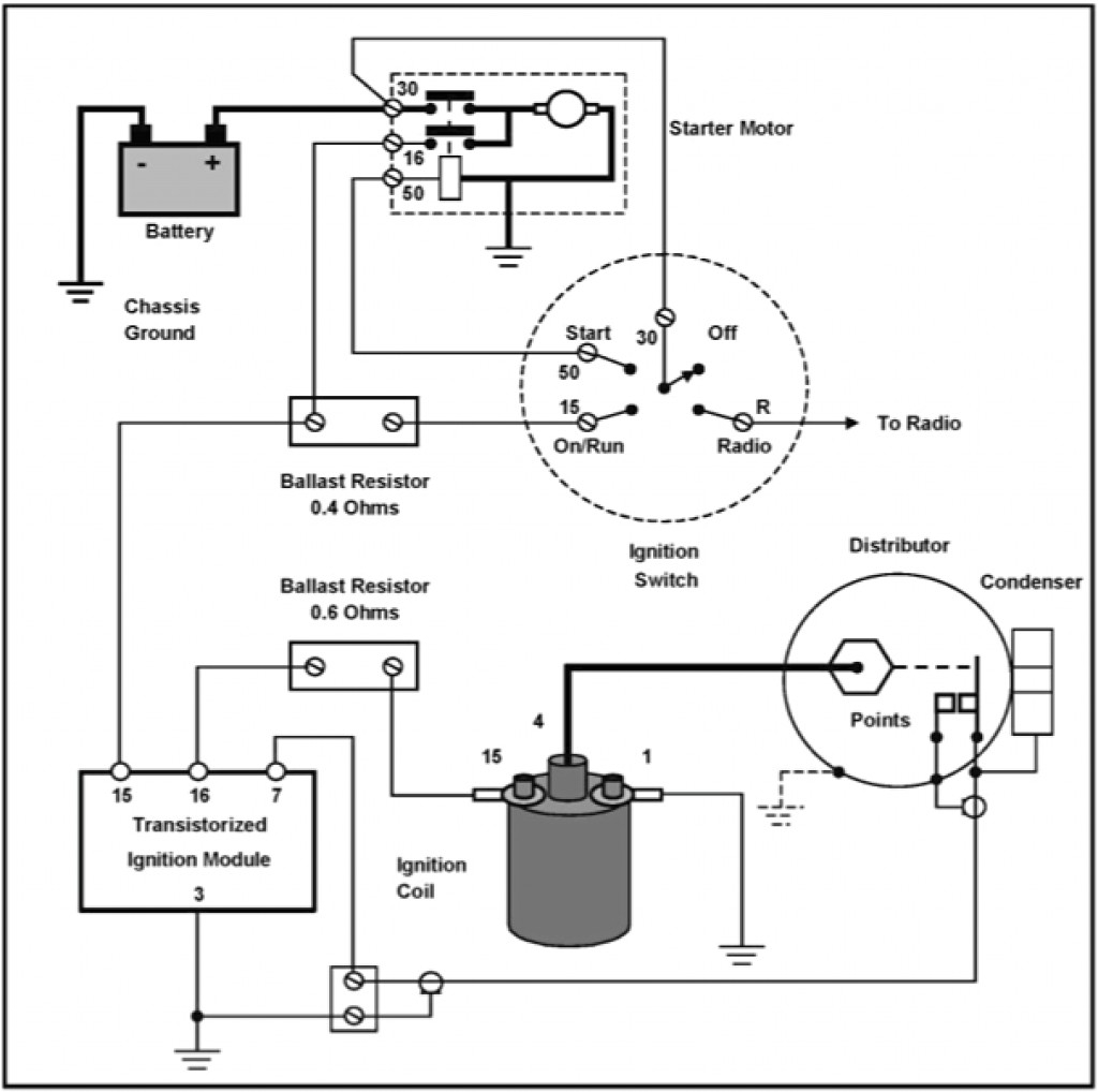
3 Pin Ignition Coil Wiring Diagram : 3 Pin Ignition Coil Wiring Diagram - Wiring Diagram : We are able to read books on our mobile, tablets and kindle, etc.. An ignition coil (also called a spark coil) is an induction coil in an automobile's ignition system that transforms the battery's voltage to the thousands of volts needed to create an electric spark in the spark plugs to ignite the fuel. Check for 0.1 ohm ~ 1.0 ohm across the two primary coil terminals. Ignition outputs (coils or ignition module driver(s)). These coils are known as smart coils and have an inbuilt igniter. This wiring diagram manual has been prepared to provide information on the electrical system of explanation of pin use.
You don't have that anymore, so you need an additional wire to. Prerequisite to the follow up ignition trouble. An ignition coil (also called a spark coil) is an induction coil in an automobile's ignition system that transforms the battery's voltage to the thousands of volts needed to create an electric spark in the spark plugs to ignite the fuel. Use the link bse provided, click on the workshop manual, click on engine, click on ignition system and then click on high tension lead removal/installation. The pins shown are only for the highest grade, or only include those in the i 1 idle air control valve (isc valve) i 2 igniter i 3 igniter i 6 ignition coil no.
Model A Ford Ignition Wiring Diagram - Wiring Diagram Schemas from i.stack.imgur.com These coils are known as smart coils and have an inbuilt igniter. This should be used to confirm the findings in the first method. The wiring diagram attached shows the general wiring for a v2.2 or a v3.0 pcb megasquirt, when installed on. Prerequisite to the follow up ignition trouble. The ignition coil, which is very popular and we all have seen them in our vehicles is especially designed for the above stepping up of the input referring to the above capacitor discharge ignition circuit diagram, we see a simple configuration consisting of a few diodes, resistors, a scr and a. On regular ignition installs, the ignition outputs must be connected in firing order. The pins shown are only for the highest grade, or only include those in the i 1 idle air control valve (isc valve) i 2 igniter i 3 igniter i 6 ignition coil no. Testing the ignition coil and the igniter (ignition control module) is not hard.
Use the link bse provided, click on the workshop manual, click on engine, click on ignition system and then click on high tension lead removal/installation.
You don't have that anymore, so you need an additional wire to. Learn about the wiring of gm hei ignition distributors with our diagrams and guide. On a factory hei, the primary coil leads will either be white and red, or yellow and red. Coil induction & wiring diagrams. The 3 prong dryer wiring diagram here shows the proper connections for both ends of the circuit. A relay is switched by electrical power and not a human. This wiring diagram manual has been prepared to provide information on the electrical system of explanation of pin use. Create a jumper wire from pin #4 directly to a good grounding spot on the engine. An ignition coil (also called a spark coil) is an induction coil in an automobile's ignition system that transforms the battery's voltage to the thousands of volts needed to create an electric spark in the spark plugs to ignite the fuel. Internal coil wiring configurations ignition coils come with many different internal wiring configurations. There are three different treble bleed circuits and many different recommended values for the components. The coils are 3 pin, with the connector as pictured. Single spark ignition coils, for example for audi, porsche, vw.
4.3 vortec ignition coil wiring diagram source: The pinout for these as per wiring the coils varies dependant on your ecu's capability. It is connected to pin3 on a db9 connector (pin2 on a. 1 i 7 ignition coil no. Ignition outputs (coils or ignition module driver(s)).
LSx coil thread - Page 3 - Miata Turbo Forum - Boost cars ... from www.miataturbo.net Create a jumper wire from pin #4 directly to a good grounding spot on the engine. Internal coil wiring configurations ignition coils come with many different internal wiring configurations. Msd ignition will accept no liability for custom applications. Diagram 2 in this circuit, a resistor is connected in parallel with the capacitor, and as the volume is turned lower, the higher frequencies are not as dominant. Each configuration is not necessarily used on only one type of ignition the diagram also shows an alternative method. 3 pin fan connections *cable coloring varies from fan to fan. It is connected to pin3 on a db9 connector (pin2 on a. You don't have that anymore, so you need an additional wire to.
See the ignition wiring section for detailed wiring.
You can download all the image about home and design for free. That shows what color wire connects to which coil? Coil induction & wiring diagrams. 3 pin fan connections *cable coloring varies from fan to fan. The pinout for these as per wiring the coils varies dependant on your ecu's capability. An ignition coil (also called a spark coil) is an induction coil in an automobile's ignition system that transforms the battery's voltage to the thousands of volts needed to create an electric spark in the spark plugs to ignite the fuel. Ignition outputs (coils or ignition module driver(s)). With this kind of an illustrative guidebook. Check for 0.1 ohm ~ 1.0 ohm across the two primary coil terminals. The following overviews each coil pin: Anyone know why the ignition coil (on plug) needs to have 3 pins connector? I had one wired to ign, pin 36 and the other to iac2b, pin 31. This post is called ignition coil wiring diagram.
Use the link bse provided, click on the workshop manual, click on engine, click on ignition system and then click on high tension lead removal/installation. The coils are 3 pin, with the connector as pictured. Parallel relationship is much more complicated compared to show one. I had one wired to ign, pin 36 and the other to iac2b, pin 31. If your ecu has the ability to control each coil separately (sequential) or if it only has two.
Basic Ignition Coil Wiring Diagram from schematron.org An ignition coil (also called a spark coil) is an induction coil in an automobile's ignition system that transforms the battery's voltage to the thousands of volts needed to create an electric spark in the spark plugs to ignite the fuel. Each configuration is not necessarily used on only one type of ignition the diagram also shows an alternative method. The following overviews each coil pin: Beru offers workshop professional three special ignition coil pullers for volkswagen group applications that are especially adapted to the geometry of ignition. This simplified wiring diagram of the ignition system applies only to 1992, 1993, 1994 and 1995 2.2l toyota camry. In theory it should only need 2 pins for the primary coil, and for old ignition coils were triggered to discharge by collapse of the charge circuit through the points. Anyone know why the ignition coil (on plug) needs to have 3 pins connector? A relay is switched by electrical power and not a human.
Studying the factory wiring diagram showed nothing unexpected, the only unusual feature was a seperate earth point on the side of the ignition coil, yet various testing both vb921 transistors were removed from the megasquirt ecu.
We are able to read books on our mobile, tablets and kindle, etc. There are three different treble bleed circuits and many different recommended values for the components. The wiring diagram attached shows the general wiring for a v2.2 or a v3.0 pcb megasquirt, when installed on. Wiring diagram for single spark ignition coil. The following overviews each coil pin: 1 i 7 ignition coil no. Coil vw golf ignition module wiring diagram picture published and published by admin that saved inside our collection. Does anyone have a wiring diagram? Wiring diagrams and tech notes. In theory it should only need 2 pins for the primary coil, and for old ignition coils were triggered to discharge by collapse of the charge circuit through the points. Being very careful not to deform or break the pin, remove the #5 wire from the cdi plug at the harness. These coils are known as smart coils and have an inbuilt igniter. Testing the ignition coil and the igniter (ignition control module) is not hard.
Coil induction & wiring diagrams amazon printed books wwwcreatespacecom/3623928 amazon kindle edition ignition coil wiring diagram. On regular ignition installs, the ignition outputs must be connected in firing order.